
Having explained how LED works, but why, do we need to bother with LED Matrix, This is because there are only so many Pinouts that can be used. Furthermore, for additional LED, the tracing becomes exponentially complex.
Driving Individual LED
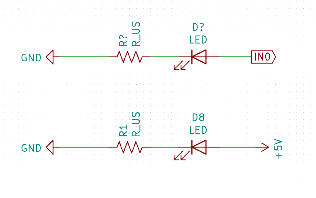
In Electronic, driving a single individual LED can be done by attaching the LED to its positive voltage and ground respectively.
The following is a simple example of LED connected either a voltage source directly, used for instance to show a device is powered. Alternatively, the LED is connected to some PIN that can be used to determine when the LED shall be lit, that is to say, driving the LED.
Driving with Shift Registers
A simple way to get an additional PIN for controlling LED can be done with Shift-registers. Each PIN of the Shift register can be attached to a single LED, followed by connected to the ground. The following shift registers are 74LS595D, which has to be driven with an external clock and data signal and etc, see datasheet for more.
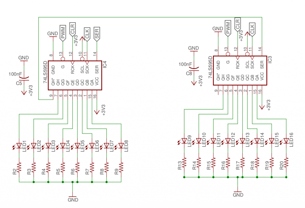
Final node, some shift registers are very cheap, thus allowing to add multiple without affecting the cost too much either. Thus, shift registers are a simple method to get additional pins for your circuit.
Driving LED MATRIX
Now, how can we drive with a LED Matrix? If you have knowledge or experience of PWM (Pulse With modulation), then you know perhaps what we can do to solve the problem. PWM will turn a voltage source from low to high, usually zero to VCC, many times per sec. More exact, by the frequency of the signal, so basically, it will look like a binary signal, where the ratio of low and high length is defined by the duty cycle.
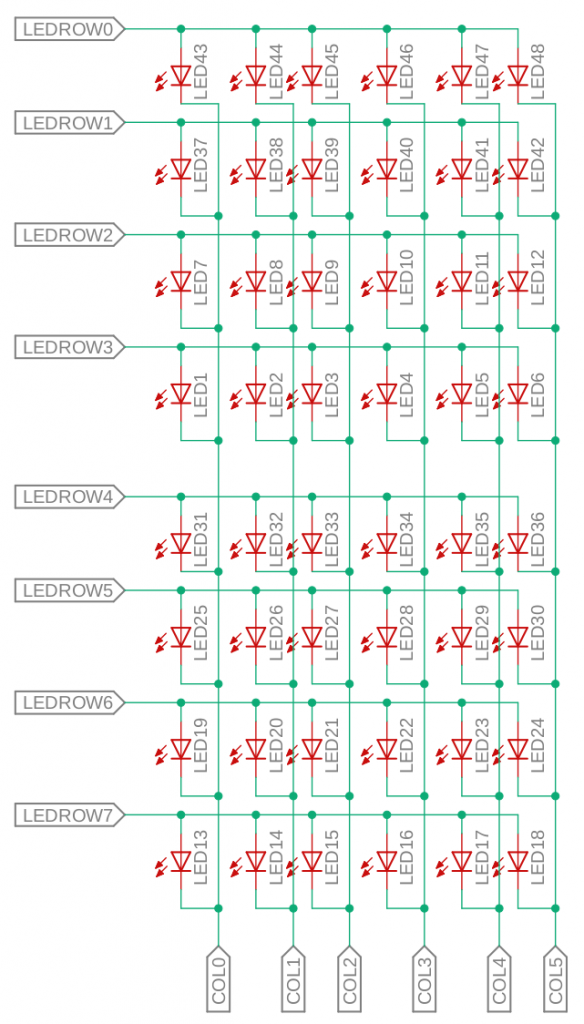
So, how does it relate to the LED Matrix then? By making only a single row being active at any given point, where the column drive which LEDS for each should be active. By doing this at a high frequency will make the LED Matrix look like they are all emitting at the same time. Similar to how PWM with a LED at a high frequency will be perceived as continuously lit, but with certain light intensity related to the duty cycle.
Driving LED Matrix
Alright, the LED matrix is configured, but how do we drive the LED matrix that would allow us to set individual LEDs.
Combing with Shift Registers
Perhaps you had the same idea. Can we not just use the shift registers directly with the LED matrix configuration, in the previous figure. The answer is correct.
By attaching the shift registers to both the row and column they could set each row at a time. Though, of course, the number of LEDs will be limit to the update frequency and what the shift registers can handle.
Driving with MCU – (Micro Controller Unit)
Of course, a simple way would perhaps be to have access to some kind of MCU, like Arduino with an Atemga MCU or something similar, and use its digital pins to drive it with some simple code logic, instead of having to write code that works with the shift registers correctly. Though, as with the shift registers, the number of LEDs that it can driven is proportional to how many digital pins and its speed.
For instance, the Arduino UNO board can have up to 24 digital pins in total if using all the IO pins. This would be up to 144 LED in a square matrix configuration, 12×12.
LED MATRIX SCHEMATIC


Support me by donation or by using the Affiliate links for your next purchase to help maintain this website.


Free/Open software developer, Linux user, Graphic C/C++ software developer, network & hardware enthusiast.